Carbon Capture - Hyjack : Hydrogen Online
Log in to start sizing and costing the Carbon Capture.
About Tech
Introduction
The reduction of greenhouse gas especially Carbon dioxide, which is the largest contributor to
global warming, is one of the main challenges for the industry sector. CO2 is mainly produced from
the post-combustion processes. Carbon capture and utilization (CCU) is an important emissions
reductions technology that will play an important role to achieve the target of zero CO2 emissions
for the industry sector.
Three basic methods are used to separate CO2 from gas streams: separation with sorbents or solvents,
with membranes or by cryogenics distillation processes. Commercially, the most well-established
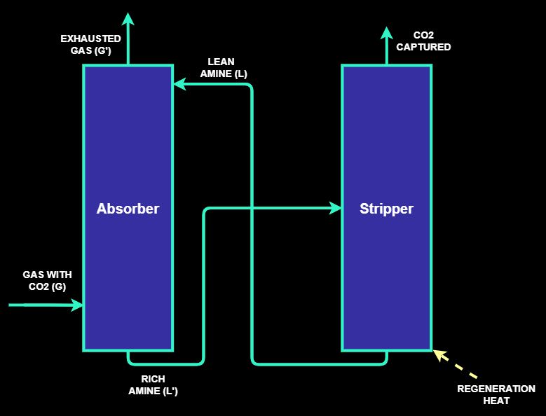
technology for CO2 capture is the amine scrubbing technology which is based on two main sections:
the chemical absorption of CO2 by an amine solution and a stripping section where the amine is
regenerated as shown in the following figure.
The Carbon Capture model aims to:
- Develop a correlation between feed gas flowrate, feed gas composition, CO2 capture efficiency, length and diameter of the absorption and stripping columns, number of columns, amount of make-up solvent and power consumption.
- Estimate the cost of a carbon capture process using amines.
CO2 can be captured either from flue gas or another process stream.
Before the carbon capture process, CO2 – containing stream is cleaned to eliminate particles such as
dust or tar or other types of particles. The clean gas and the amine solution are then injected in the
absorption column in counter current. The absorber is filled with packings to optimize the gas/liquid
contact.
The pure gas is recovered at the top of the column while the amines rich with CO2 are recovered at the
bottom of the column and then preheated to 100°C in a cross-heat exchanger before injection into the
stripper. The heat exchange occurs thanks to the hot stream of regenerated amine leaving the stripper.
After the stripping step, the CO2 is dried and compressed to meet the required pressure for
its transportation and storage.
Process Chemistry
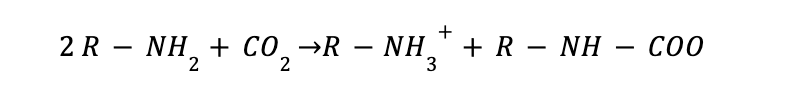
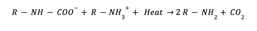
Carbon capture with amine is indeed a chemical absorption process with a complex chemistry behind. The amine reacts with the CO2 to produce an intermediate compound called carbamate. The formed compound dissociates to give back CO2 and the amine solvent by the application of heat. However, the carbamate needs to be stable, and it is granted by using unhindered amines such as MEA amine. A representation of the main reactions involved in the process are shown below.
CO2 Absorption
MEA Regeneration
Sizing of the columns :
The main equipment to be sized in a carbon capture process with amine are the absorption and stripping columns.
ABSORBER
Sizing of the absorber columns is defined by the diameter and length of the vessel.
To define the calculations, a gas inlet temperature of 55 ◦C and 1.2 bar as pressure are settled.
Before the sizing, some material balances and compound properties calculations are done.
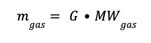
The molecular weight of the gas mixture (MWgas) is determined by applying the equation below.
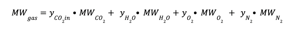
Where:
yCO2in is the CO2 composition at the inlet gas (mol/mol)
yH2O is the H2O composition at the inlet gas (mol/mol)
yO2 is the O2 composition at the inlet gas (mol/mol)
yN2 is the N2 composition at the inlet gas (mol/mol)
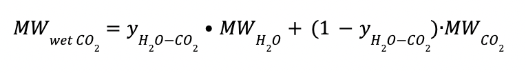
MWCO2 is the CO2 molecular weight (44 kg/kmol)
MWH2O is the H2O molecular weight (18 kg/kmol)
MWO2 is the O2 molecular weight (32 kg/kmol)
MWN2 is the N2 molecular weight (28 kg/kmol)
The gas flow rate in kmol is defined as:
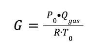
Where:
P0 is the pressure at normal conditions (1 bar)
Qgas is the total gas flowrate at the inlet of the absorber (Nm3/h)
R is the ideal gas constant (0.08314 m3 bar / K kmol)
T0 is the temperature at normal conditions (273.15 K)
The gas flow rate in kg is defined as:
The L/G ratio (mol/mol) in the absorption column is estimated as:
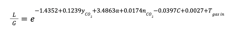
Where:
α is the CO2 loading in lean amine, established as 0.2 mol CO2 / mol MEA
nCO2 is the CO2 capture efficiency
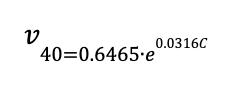
C is the amine concentration in % w/w (compositions between 15 – 40 % w/w)
Tgas in is the inlet gas temperature in K
L is the liquid flowrate in kmol/h
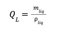
The liquid flowrate in kg (mliq) is calculated as:
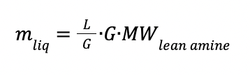
With:
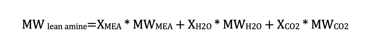
Where:
XMEA is the MEA composition in the lean amine (mol/mol)
XH2O is the H2O composition in the lean amine (mol/mol)
XCO2 is the CO2 composition in the lean amine (mol/mol)
MWMEA is the MEA molecular weight (61 kg/kmol)
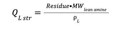
MWlean amine is the average molecular weight for lean amine
The viscosity of the liquid in Pa∙s at 40 ◦C is calculated as:
The gas mixture density (gas) is determined using an approximation to an ideal gas behaviour due to the low operating pressure.
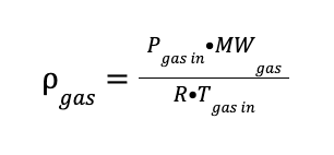
Where:
Pgas in is the inlet gas pressure in bar
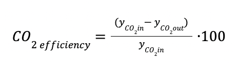
The CO2 captured in kmol / h is equal to:
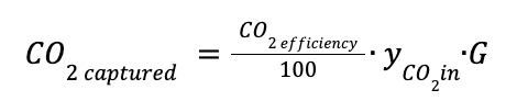
CO2 efficiency is the percentage of CO2 recovered.
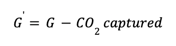
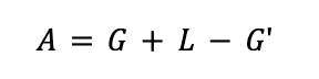
The outlet gas from the absorber (G') is defined as:
Absorber diameter
To estimate the absorber diameter, the following correlations is applied:
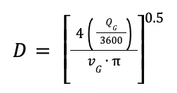
Where:
vG is the velocity of the gas in m/s
QG is the volumetric flowrate of the gas in m3/h
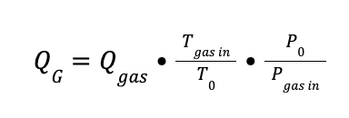
To estimate the velocity of the gas (vG), the subsequent calculations were considered:
The flow parameter (X) is defined as:
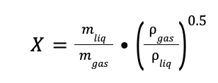
Where:
mgas is equal to the total gas (mol flow) per MWgas
mliq is the liquid flowrate in kg/h
ρliq is the density of the liquid (1000 kg/m3)
The pressure drop parameter and the coefficient under flooding conditions are estimated by two correlations.
The pressure drop:
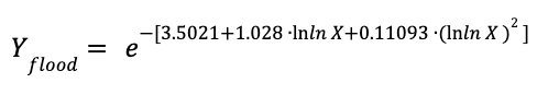
The coefficient under flooding conditions
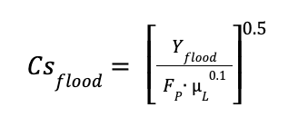
Where:
Yflood is the pressure drop parameter under flooding conditions
Csflood is the coefficient at flooding conditions
FP is the pressure factor of the packing. For metallic rasching rings - 1-inch packing, Fp was considered equal to 85 ft-1
μL is the viscosity of the liquid in Pa∙s
Finally, the gas velocity at the flooding conditions and the gas velocity are calculated as follow:
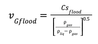
and
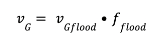
Where:
vGflood is the gas velocity at the flooding conditions
fflood is the flooding factor, defined as 70 %
Absorber length
The height of the packing in the column can be estimated as follows:
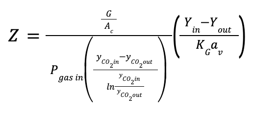
Where:
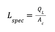
Ac is the cross-section area of the column in m2
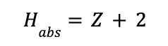
Z is the packing height of the column in m
and
KGav is the volumetric mass transfer coefficient in kmol/ (m3 kPa h)
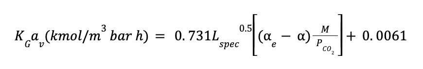
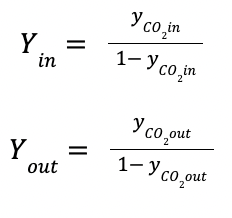
Where:
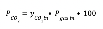
PCO2 is the CO2 partial pressure in KPa, defined as:
M is the lean MEA concentration in kmol / m3
Lspec is the specific flow rate in m3 / m2 h, defined as :
The total height of the absorption column (Habs) is found by adding 2 m to the packing height.
STRIPPER
For the stripper, the column works at 1.5 bar and a temperature at the top and bottom of 100 and 120 ◦C
respectively.
The total flowrate at the feed of the stripper is estimated by a material balance in the absorber.
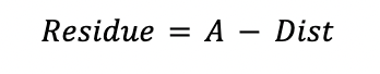
The distillate containing the CO2 recovered (Dist) is calculated by a material balance in the stripper.
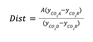
Where:
yCO2A is the CO2 composition at the feed of the stripper
yCO2D is the desired distillate CO2 composition in the stripper
yCO2R is the CO2 composition in the residue of the stripper (CO2 composition of the lean amine)
Stripper diameter
The diameter of the stripper is defined by the tray with the greatest vapor load.
The maximum vapor load (VL) is estimated by considering the wet CO2 vapor at the top temperature of
the stripper.
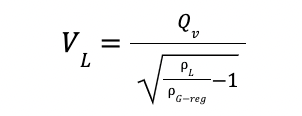
With
And
And
Where:
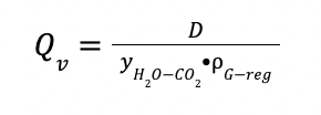
VL is the vapor load in m3 / h
Qv is the vapor flowrate in m3 / h
yH2O-CO2 is the H2O composition in CO2-rich phase at 100 ◦ C
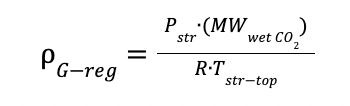
ρG-reg is the gas density in the stripper
MWwet CO2 is the average molecular weight of the wet CO2
Pstr is the operating pressure of the stripper
Tstr-top is the temperature at the top of the stripper
Approximation of the internal diameter Di at the level of the design tray
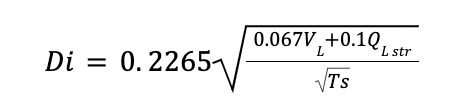
With
And
And
Where:
QL str is the liquid flowrate in the stripper
Residue is the residue flowrate in the stripper in kmol /h
Ts is the spacing between trays. Since internal diameters are established between 1.2 and 3 m, spacing of 0.6 is fixed.
Stripper height
For cost estimation purposes, the height of the stripping column was considered similar to the absorber height (5 % smaller). Note that the number of absorption (Nabs) and stripping columns (Nstr) are defined by the calculated diameter of each process in meters divided by 3 m.
Utilities consumption
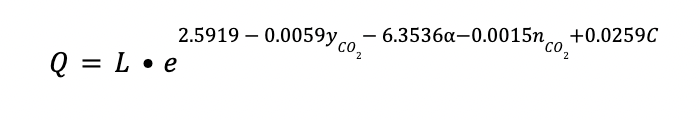
Regeneration heat
The regeneration of the amine consumes a considerable amount of energy. It is obtained by the following correlation:
Where:
Q is expressed in GJ/h
MEA make-up
During the CO2 process, there are some MEA losses due to acid gases, oxidation, HSS formation
or with gas exhausted. It is estimated a make-up of 1.5 kg of MEA / ton CO2 captured.
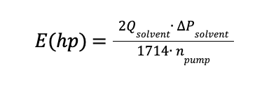
Electrical Power
Electrical Power associated to the pumps needed in the process are estimated as follow:
Where:
Qsolvent is the solvent flowrate in gal/min
∆Psolvent is 30 psi
About costing
The costing is expressed at two different levels:
- The equipment cost, related to the total carbon capture plant. Compression step and cost of the packing are not included on it.
-
The total cost represents the sum of the equipment cost and the auxiliary costs.
The latter can be significative, it includes an estimation of engineering, civil works,
transportation, instrumentation and piping costs. Total cost is expressed as a range,
with a low and a high estimation both calculated as a percentage (%) of the equipment cost.
The low estimate of the total dispenser cost is set to a sum of the equipment cost plus an
additional 50 %. The high estimate of the total cost includes the equipment cost plus an additional 123 %.
Note that the total cost doesn't include contingencies and owner's costs.
The carbon capture cost is based on the price of the columns.
To determine the cost of the columns it is necessary to know their weight. For that, the following steps are listed:
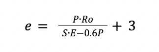
Calculation of the thickness
Where:
e is the thickness in mm
P is the operating pressure 10 % greater in bar
Ro is the radius of the vessel in mm
S is the maximum stress permissible for the material, considered as 1000 bar for carbon steel.
E is the weld factor which it is equal to 0.85
Determination of the weight
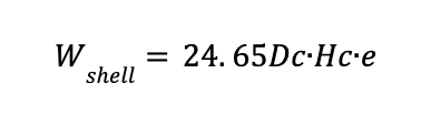
1 - Weight of the cylindrical shell (Wshell)
Where:
Dc is the diameter of the column in m
Hc is the height of the column in m
Wshell is the cylindrical shell weight in kg
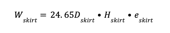
2 - Weight of the skirt (Wskirt)
Where:
Dskirt equal to Dc
Hskirt is assumed to be equal to 3 m
eskirt is assumed to be equal to 10 mm
Wskirt is the skirt weight in kg
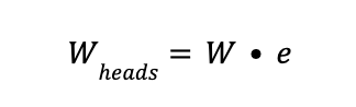
3 - Weight of the heads of the cylindrical shell (Wheads)
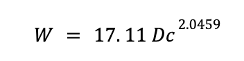
with
Where:
W is the weight of 1 mm thickness head
The reference cost of the head, skirt and cylindrical shell (C) is obtained by the expression:
Where fe is a correction factor as a function of the thickness.
It can be calculated as:
Also ff depends on the cylindrical shell diameter:
ff = 2.5 for a D between 1.2 and 1.5 m
ff = 2 for a D between 1.5 and 2 m
ff = 1.5 for a D higher than 2 m
Last step to calculate the total cost consists on calculationg CA
The total cost of the absorber and stripper are estimated as:
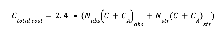
Where:
Nabs is the number of absorption columns in the system
Nstr is the number of stripping columns in the system
The cost of the columns represents a given percentage of the total cost, depending on the CO2 inlet gas composition.
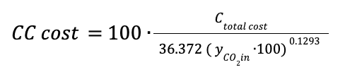
Where CC cost is the total cost of the carbon capture system in euros.
Accuracy Level
An accuracy level is added to reflect the accuracy and precision of the results and cost equations.
An accuracy level of “Fair” (Accuracy Index of 3/3) is to reflect that for this technology and sizing, the available data is sufficient to consider the costing used.
An accuracy level of “Projected” (Accuracy Index of 2/3) is given to reflect that the costing computed might rely on insufficient sources for this technology and sizing. The lack of data may reflect either that the technology is still under development and thus the results are projections of reachable costs in the future, or the sizing computed doesn't correspond to a configuration where this technology is usually deployed.
An accuracy level of “Improvable” (Accuracy Index of 1/3) is given to reflect that the costing computing might rely on an insufficient number of sources for this technology and sizing. To enhance the costing for this configuration, your feedback is welcome.
Sources
REPORTS:
- IECM Technical Documentation (2019) - Amine-based Post-Combustion CO2 Capture
- Trimery Corporation (2007) - Advanced Amine Solvent Formulations and Process Integration for Near-Term CO2 Capture Success
SCIENTIFIC PAPERS:
- J. Husebye et al, Techno economic evaluation of amine-based CO2 capture: impact of CO2 concentration and steam supply (2012)
- J. Huertas et al, CO2 Absorbing Capacity of MEA (2015)
- M. Afkhamipour et al, Review on the mass transfer performance of CO2 absorption by amine-based solvents in low- and high-pressure absorption packed columns (2017)
- S. Cohen et al, Comparing post-combustion CO2 capture operation at retrofitted coal-fired power plants in the Texas and Great Britain electric grids (2011)
- U. Aronu et al, 1st Post Combustion Capture Conference Equilibrium in the H2O-MEA-CO2 system: new data and modelling.
- A. Perez et al, Design of a packed bed absorption column considering four packing types and applying MATLAB (2018)
- J. Yuanhui et al, Progress in the Study on the Phase Equilibria of the CO2-H2O and CO2-H2O-NaCl Systems (2007)
- L. Li, The Henry Coefficient of CO2 in the MEA-CO2-H2O System (2017)
- U. Arachchige, Viscosities of Pure and Aqueous Solutions of Monoethanolamine (MEA), Diethanolamine (DEA) and N-Methyldiethanolamine (MDEA) (2013)
- U. Arachchige, Viscosities of Aqueous Solutions of Monoethanolamine (MEA), Diethanolamine (DEA) and N Methyldiethanolamine (MDEA) at T = (90-150) °C (2014)
- Alain Valtz, Vapour–liquid equilibria in the carbon dioxide–water system, measurement and modelling from 278.2 to 318.2K (2004)
